

During internship OTA development on an STM32G0 board, I ran into several issues and summarized the fixes, mainly around Bootloader jump logic and APP partition strategy.
- The system hangs after Bootloader jumps to the APP region.
- With dual APP partitions, Bootloader can jump to only one partition instead of both.
System Hangs After Bootloader Jump
First, let's briefly explain the mechanism of jumping to an application. It involves setting the PC pointer position and the stack pointer position. The address the PC pointer points to should be \([\text{program flash address}] + 4\). For development boards with the CBT6 suffix, you can refer to the following HAL library code:
1 |
|
Of course, we can directly use the code
above to perform the jump, provided that the address pointed to by addr
exists in RAM. In actual execution, it was found that the program
successfully jumped and ran, but it would hang somewhere and fail to
proceed. The reason is simple: we redirected the PC pointer and the
stack pointer, but did not relocate its interrupt vector pointer.
As a result, when the APP encounters an interrupt function during
execution, it jumps back to the Bootloader's interrupt vector table,
naturally causing the program pointer to run astray. By default, the
program's interrupt vector table pointer points to 0x0, but in reality,
the starting position of the corresponding interrupt vector table for a
program is the program's starting address. Refer to the diagram below:
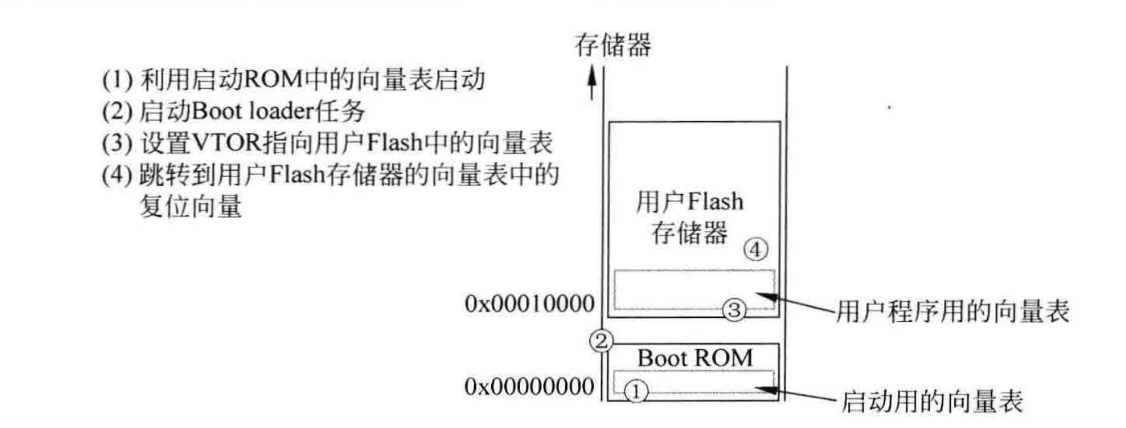
Solution
In Cortex-M series chips, except for the M0, all chips retain the VTOR register for relocating the interrupt vector table. The G0 series development board uses an M0+ core, which supports this register. Therefore, before jumping to the program, simply assign the corresponding address to the VTOR register. Based on the diagram above, the vector table address is the start address of the program. The complete jump function code is as follows:
1 |
|
In other projects, I have also encountered situations where OTA had to be implemented on M0 series chips. When registers cannot be configured directly, it becomes slightly more troublesome: we need to manually relocate the interrupt vector table. The general idea is to copy the entire interrupt vector table into RAM before jumping, and then remap the vector table pointer address to the base address of RAM (mapped to 0x20000000 according to the example above). A remap function in the corresponding STM32 library is typically used here. Unfortunately, because the board I developed did not use the STM standard library and lacked the corresponding function, I have not yet found another way to implement this feature. If needed, you can look up relevant documentation on implementing Bootloaders for the M0 series; since I have not verified it in practice, I will not discuss it further here.
Bootloader Can Only Jump to One Partition in a Dual-APP Setup
A dual-APP partition setup was the first method I conceived to achieve OTA without an external EEPROM, dividing the flash into Bootloader + Flag + Region A/B. The OTA update logic goes as follows: 1. The program enters Region A by default on startup; 2. An OTA request occurs, and the new program is written to Region B; 3. Once writing succeeds, the flag corresponding to the address in the Flag region is set to valid; 4. Force the program into an infinite loop and let the watchdog reset the system; 5. After the Bootloader verifies the program, it jumps to Region B to execute, while Region A becomes the new download region.
The advantage of this approach is that it always ensures one partition contains executable code. Even if OTA fails or the write process is forcibly interrupted, there remains a valid partition to run. In addition, it makes effective use of program flash space, reduces the erase/write cycles for a single region, and prolongs flash lifespan.
However, the above approach overlooks the issue of program address
pointers. After compiling with various toolchains, the resulting binary
executable actually retains information such as the program's starting
address. This address information is generally located at the beginning
of the bin file (which is also the interrupt vector table address
mentioned in the previous issue). When hardware executes the bin
program, it first reads this address information and jumps to the
corresponding location to execute. In fact, if we configure different
flash addresses for the same program, the generated bin files will be
different. The comparison below illustrates this clearly: 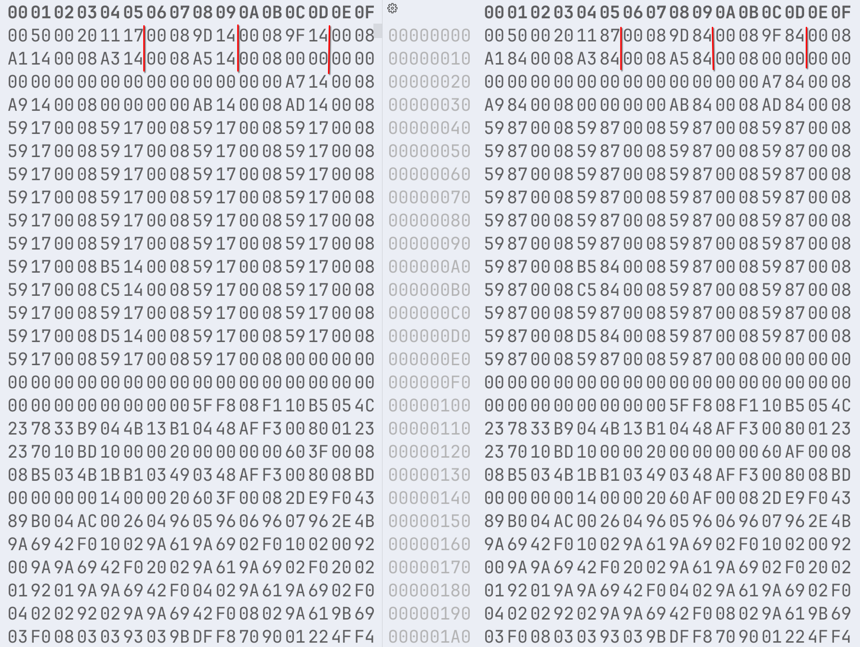 From the differences between the
partitioned data segments, the difference in the header data segments is
obvious. If we simply flash the exact same binary (compiled for a
specific flash region) into different regions, even if the Bootloader
jumps to the correct address, interrupts will jump back to the original
region when the program reads its initial header fields. This means that
when compiling a new program, we must know the target flash address
beforehand; otherwise, partition jump errors will occur. This is very
inconvenient for subsequent OTA updates, so this method cannot be used
directly.
Solutions
1. Modifying Header Fields in the Program [Not Reusable]
This method involves modifying the header fields of the pending OTA program within the code based on the OTA target address stored in the flag region. As seen from the comparison data in the image above, the header fields repeat a certain field value within a specific range. This value is roughly \(\text{program flashing target address} + \text{a certain offset}\). However, I haven't found a fixed pattern for this offset yet, as it seems to vary across different programs. Given that projects should eliminate such unstable factors as much as possible, this solution was temporarily abandoned.
2. Revised Solution: Application Region + Download Region
In short, the goal is to avoid jumping to different regions and instead fix the startup jump to a single region whenever possible. Region A is configured as the APP region. When OTA is performed, the program is downloaded into Region B, and the OTA flag along with CRC checksum information are written to the flag region, followed by a watchdog reset. The Bootloader program verifies the validity of the program in Region B, copies it to Region A for execution, and then resets the flag region.
Of course, this solution comes with operational stability trade-offs: Bootloader startup latency increases when OTA is required, and ensuring the integrity of the copied program is challenging. Therefore, it is best to use an external EEPROM or flash to handle temporary storage of OTA binaries.